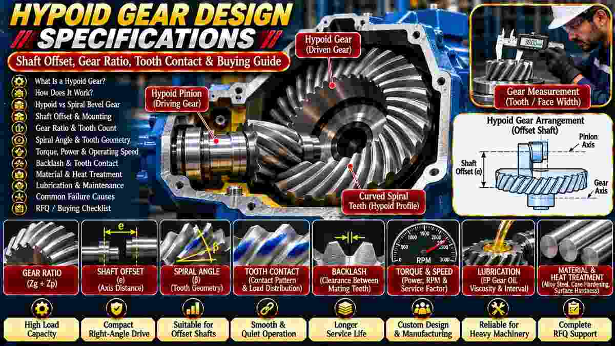
Are you sourcing hypoid gears for an industrial gearbox, conveyor drive, or custom power transmission system? Incorrect shaft offset, tooth geometry, or mounting dimensions can cause gear noise, poor tooth contact, excessive heat, and premature wear.
Hypoid gear design specifications should include shaft offset, gear ratio, tooth count, spiral angle, torque, operating speed, mounting distance, backlash, material, heat treatment, and lubrication requirements.
Asar Engineering Pvt. Ltd. manufactures industrial transmission components, including hypoid gear sets made to customer drawings or samples.
What Is an Industrial Hypoid Gear?
A hypoid gear is a curved-tooth gear used to transmit rotational power between non-intersecting, non-parallel shafts, typically arranged at approximately 90 degrees.
Unlike conventional spiral bevel gearing, the pinion axis is positioned above or below the larger gear's axis.
Typical applications include:
-
Industrial right-angle gearboxes.
-
Conveyor drives.
-
Material-handling machinery.
-
Specialized speed reducers.
-
Heavy-duty transmission systems.
Explore Hypoid Gears for product information.
How Does a Hypoid Gear Work?
A hypoid gear set transfers torque through curved teeth that engage progressively while combining rolling and sliding contact.
The smaller pinion drives the larger gear, providing a selected speed ratio.
The shaft offset influences the tooth geometry, bearing loads, and sliding conditions.
Both gears must be manufactured and installed as a compatible pair.
What Is the Difference Between Hypoid and Spiral Bevel Gears?
Hypoid gears operate on offset, non-intersecting shaft axes, while conventional spiral bevel gears operate on intersecting axes.
Hypoid designs can provide greater flexibility in shaft positioning and potentially higher load capacity for suitable arrangements.
However, their increased sliding contact places greater demands on lubrication and tooth-surface design.
Explore Spiral Bevel Gears for related products.
Why Is Shaft Offset Important in Hypoid Gear Design?
Shaft offset is the shortest distance between the two gear axes and is a defining dimension of a hypoid gear set.
It affects:
-
Pinion positioning.
-
Tooth geometry.
-
Gearbox layout.
-
Sliding velocity.
-
Bearing loads.
-
Contact patterns.
Increasing the offset without redesigning the gear geometry can cause incorrect meshing.
Always specify the required offset and its direction on the engineering drawing.
How Do You Calculate the Hypoid Gear Ratio?
The nominal reduction ratio is calculated by dividing the number of teeth on the larger driven gear by the number on the driving pinion.
Gear Ratio = Gear Teeth ÷ Pinion Teeth
For example, a 40-tooth gear paired with a 10-tooth pinion provides a nominal 4:1 reduction ratio.
For replacement applications, retain the approved tooth counts unless the complete transmission is being redesigned.
Why Are Spiral Angle and Tooth Geometry Important?
Spiral angle and tooth geometry influence meshing, contact distribution, sliding behavior, and operating loads.
Important specifications include:
Hypoid tooth geometry is more complex than that of conventional spur gears.
An approved tooth design or complete matched gear sample is preferable to isolated dimensional estimates.
How Do Torque and Operating Speed Affect Gear Selection?
Torque and speed determine important mechanical loads and influence tooth strength, bearing requirements, and thermal performance.
For preliminary torque estimation:
Torque (Nm) = 9550 × Power (kW) ÷ RPM
Final selection must also account for:
-
Starting torque.
-
Shock loading.
-
Duty cycle.
-
Operating efficiency.
-
Service factors.
-
Reversing conditions.
The complete gearset must satisfy the required operating loads.
Why Are Mounting Distance and Backlash Important?
Mounting distance establishes the installed position of each gear, while backlash provides the necessary clearance between mating teeth.
Incorrect mounting can shift the contact pattern toward the tooth edges.
Insufficient backlash may lead to binding and overheating.
Excessive backlash can increase noise and affect positioning accuracy.
Follow the gear manufacturer's approved assembly dimensions.
How Should Hypoid Gear Tooth Contact Be Inspected?
Tooth contact should be evaluated using an appropriate inspection method to confirm that the mating gears engage as intended.
Common checks include:
Inspection should address the applicable drive and coast flanks.
A satisfactory contact pattern depends on the complete assembly.
Which Materials Are Suitable for Hypoid Gears?
Hypoid gear materials should be selected according to transmitted load, contact stress, fatigue resistance, wear, and operating conditions.
Depending on the design, manufacturers may use suitable alloy steels with specified heat treatment.
Important requirements include:
Material and heat-treatment specifications should come from approved engineering calculations.
Why Is Lubrication Critical for Hypoid Gears?
Hypoid gears experience substantial sliding contact, making suitable lubrication essential to control friction, heat, scoring, and wear.
Many applications require an appropriate extreme-pressure gear lubricant.
Confirm:
Use the equipment manufacturer's recommended lubricant rather than assuming one oil suits every application.
What Causes Premature Hypoid Gear Failure?
Common causes include incorrect tooth contact, inadequate lubrication, excessive loading, contamination, and unsuitable bearing alignment.
Warning signs include:
Inspect the gears, bearings, housing, and lubricant together.
Should Hypoid Gears Be Replaced as Matched Sets?
Replacing the pinion and larger gear together is often preferable because their tooth geometry, contact pattern, and assembly settings are closely related.
Replacing only one component may be possible after engineering evaluation, but compatibility must be established.
For worn gearsets, provide both components and relevant housing dimensions.
What Factors Affect Hypoid Gear Manufacturing Prices?
Prices depend on gear dimensions, tooth geometry, materials, heat treatment, finishing, inspection, and production quantity.
Custom manufacturing may require specialized tooling or additional engineering verification.
Compare quotations using the same approved technical requirements.
What Should You Include in a Hypoid Gear RFQ?
A complete RFQ should describe the application, gear geometry, mounting arrangement, loads, materials, and inspection expectations.
Include:
-
Machinery application and gearbox type.
-
Gear and pinion tooth counts.
-
Required gear ratio.
-
Shaft angle and axis offset.
-
Spiral angle and tooth hand.
-
Gear dimensions and face width.
-
Pinion and gear mounting distances.
-
Operating torque, power, and RPM.
-
Material and heat-treatment requirements.
-
Backlash and tooth-contact requirements.
-
Technical drawings or matched samples.
-
Quantity and delivery location.
Identify the required inspection reports and acceptance criteria.
What Are the Most Frequently Asked Questions About Hypoid Gears?
Common buyer questions concern shaft offset, replacement compatibility, lubrication, and customized manufacturing.
Can Hypoid Gears Replace Spiral Bevel Gears Directly?
No. Their shaft geometry and mounting requirements differ, so direct substitution generally requires redesign.
Do Hypoid Gears Require Special Lubrication?
They commonly require suitable extreme-pressure lubrication because of significant sliding tooth contact.
Can Hypoid Gears Be Custom Manufactured?
Yes. Custom manufacturing may be available according to approved drawings, matched samples, and supplier capabilities.
Is Shaft Offset the Same as Center Distance?
No. Hypoid shaft offset is the shortest distance between non-intersecting shaft axes, rather than the conventional center distance used for parallel-axis gears.
Can a Worn Hypoid Pinion Be Replaced Separately?
Only after verifying compatibility with the existing gear and the required tooth-contact and mounting conditions.
How Can You Request Hypoid Gears From Asar Engineering?
You can request a quotation by sharing your gear drawings, shaft offset, tooth counts, operating requirements, material specifications, and quantity.
For replacement projects, provide both mating gears or complete technical documentation where possible.
Explore Hypoid Gears or contact Asar Engineering to discuss your requirements.
Technical Note: Final hypoid gear design and manufacturing should follow approved gear geometry calculations, applicable standards, verified load requirements, and validated assembly inspection procedures.