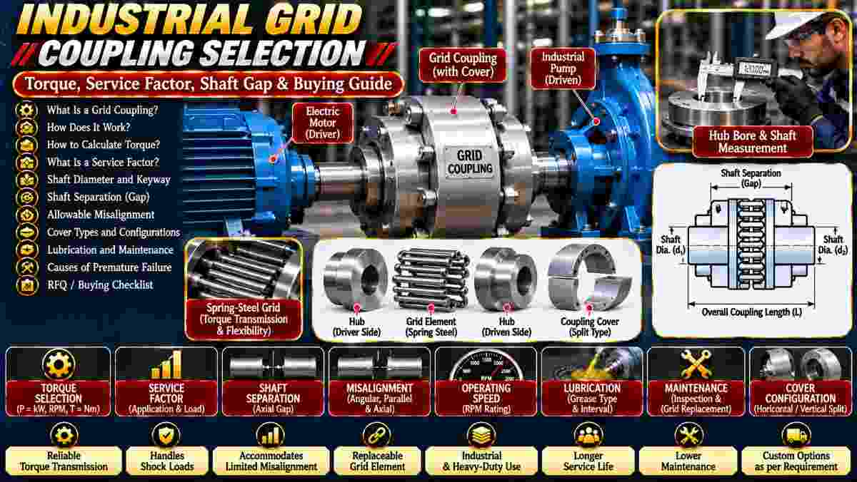
Are excessive vibration, sudden shock loads, or worn coupling elements causing problems in your industrial drive system? Selecting the wrong coupling can increase maintenance costs and shorten equipment life.
Industrial grid coupling selection depends on transmitted torque, motor power, operating RPM, service factor, shaft dimensions, allowable misalignment, and lubrication requirements.
A correctly selected grid coupling can help transmit power while accommodating limited shaft movement and cushioning certain shock loads.
Asar Engineering Pvt. Ltd. offers industrial power transmission components, including resilient grid couplings.
What Is an Industrial Grid Coupling?
An industrial grid coupling is a flexible shaft coupling that uses a metallic spring grid to transmit torque between two connected hubs.
The grid fits into grooves in the coupling hubs and provides limited flexibility during operation.
Common applications include:
Explore Grid Couplings for product information.
How Does a Resilient Grid Coupling Work?
A resilient grid coupling transmits torque through a spring-steel grid that connects the grooves of two coupling hubs.
When torque is applied, the grid transfers rotational force between the shafts.
Its flexible construction can accommodate limited shaft displacement and help cushion certain transient loads.
The coupling must remain within its manufacturer's torque, speed, and misalignment limits.
Why Are Grid Couplings Used in Heavy-Duty Machinery?
Grid couplings are used where reliable torque transmission, limited flexibility, and shock-load accommodation are required.
Potential advantages include:
-
High torque capacity in suitable designs.
-
Accommodation of limited misalignment.
-
Damping of certain vibration and shock loads.
-
Replaceable grid elements.
-
Availability of different cover configurations.
Actual performance depends on coupling size, construction, maintenance, and operating conditions.
How Do You Calculate Grid Coupling Torque?
Operating torque can be estimated from transmitted power and rotational speed.
For metric units:
Torque (Nm) = 9550 × Power (kW) ÷ RPM
For example, a 30 kW motor operating at 1,500 RPM produces approximately 191 Nm of steady-state shaft torque.
This calculation does not include starting loads, shock loads, or other transient conditions.
What Is a Service Factor in Grid Coupling Selection?
A service factor adjusts the required coupling rating to account for the operating characteristics of the connected equipment.
A preliminary selection relationship is:
Required Coupling Rating = Operating Torque × Service Factor
For example, using 191 Nm of torque and an illustrative service factor of 1.5 gives approximately 287 Nm.
The correct factor must come from the coupling manufacturer's application tables.
Why Are Peak Torque and Shock Loads Important?
Peak torque and shock loading can exceed normal operating torque and influence coupling size and service life.
Important factors include:
-
Frequent motor starts.
-
Sudden equipment jams.
-
Reversing loads.
-
High rotating inertia.
-
Repeated shock loading.
-
Braking requirements.
High-peak-load applications may require a different selection procedure from standard motor-driven equipment.
How Does Operating RPM Affect Grid Coupling Selection?
Operating speed determines whether the coupling can run within its approved mechanical and balancing limits.
Check:
Do not select a coupling using torque rating alone.
Why Are Shaft Diameter and Keyway Dimensions Important?
Shaft and keyway dimensions determine whether the coupling hubs can be securely installed on the driving and driven equipment.
Specify:
The two shafts may require different hub bore sizes.
What Is Shaft Separation in Grid Couplings?
Shaft separation is the axial distance between the opposing shaft ends when the equipment is installed.
It is also called the shaft gap or distance between shaft ends.
This dimension affects coupling installation and the selected configuration.
Provide the original shaft gap and confirm the allowable installation range from the manufacturer's drawing.
How Much Misalignment Can a Grid Coupling Handle?
Grid couplings can accommodate limited angular, parallel, and axial displacement according to their specific design.
However, allowable values vary by model and operating conditions.
Excessive misalignment can cause:
Proper shaft alignment is still required.
Which Grid Coupling Cover Type Should You Choose?
Cover selection depends on installation access, coupling construction, lubrication requirements, and maintenance needs.
Common configurations include:
Confirm the available space needed for inspection and grid replacement.
The chosen cover must be compatible with the exact coupling model.
Why Is Lubrication Important for Grid Couplings?
Lubrication helps reduce friction and wear between the metallic grid and hub grooves during operation.
Important considerations include:
Use the lubricant specified by the coupling manufacturer.
Incorrect or insufficient lubrication can accelerate component wear.
What Causes Premature Grid Coupling Failure?
Common causes include overloading, poor alignment, inadequate lubrication, damaged seals, and incorrect installation.
Warning signs include:
-
Increased vibration.
-
Unusual noise.
-
Grease leakage.
-
Damaged grid elements.
-
Worn hub grooves.
-
Loose fasteners.
Investigate the complete drive system before replacing the coupling.
What Should You Check Before Ordering a Replacement Grid Coupling?
A replacement grid coupling should match the original mechanical ratings, shaft connections, dimensions, and operating requirements.
Verify:
-
Existing coupling manufacturer and model.
-
Rated torque and RPM.
-
Motor and driven shaft diameters.
-
Bore and keyway sizes.
-
Shaft separation.
-
Hub dimensions.
-
Grid element designation.
-
Cover type.
-
Lubrication requirements.
-
Installation clearances.
Provide the original drawing or coupling identification whenever possible.
What Factors Affect Industrial Grid Coupling Prices?
Grid coupling prices depend on torque rating, size, hub configuration, materials, grid element, cover design, and order quantity.
Special bores, keyways, balancing, and inspection documentation may increase costs.
Compare quotations with the complete supply scope clearly defined.
What Should You Include in a Grid Coupling RFQ?
A complete RFQ should identify the application, torque requirements, operating conditions, shaft dimensions, and coupling configuration.
Provide:
-
Machine application.
-
Motor power in kW or HP.
-
Normal operating RPM.
-
Normal and peak torque.
-
Operating hours and starting frequency.
-
Application service factor.
-
Both shaft diameters.
-
Bore and keyway details.
-
Shaft separation.
-
Required cover configuration.
-
Environmental conditions.
-
Technical drawings, quantity, and delivery location.
These details help suppliers evaluate a suitable coupling.
What Are the Most Frequently Asked Questions About Grid Couplings?
Common questions concern torque capacity, misalignment, lubrication, grid replacement, and coupling compatibility.
Are Grid Couplings Suitable for High-Torque Applications?
Yes, when the selected coupling meets the required torque, speed, service factor, and operating conditions.
Can Grid Couplings Reduce Vibration?
They can help damp certain torsional disturbances, but they cannot correct severe shaft misalignment or other underlying machinery problems.
Do Grid Couplings Require Lubrication?
Many conventional metallic grid couplings require manufacturer-approved grease and periodic maintenance.
Can You Replace Only the Grid Element?
Some designs allow grid replacement without removing the hubs, provided the remaining components are serviceable and compatible.
Can Grid Couplings Be Customized?
Custom bores, keyways, and configurations may be available depending on supplier capabilities and approved specifications.
How Can You Request Industrial Grid Couplings From Asar Engineering?
You can request a quotation by sharing motor power, operating RPM, torque requirements, shaft dimensions, coupling configuration, and quantity.
For replacement applications, include the original coupling designation, photographs, or technical drawings.
Explore Grid Couplings or visit Asar Engineering to discuss your requirements.
Technical Note: Final coupling selection must follow manufacturer torque and speed ratings, application service factors, shaft compatibility, alignment limits, and approved installation procedures.