Explaining Industrial Transmission Gear?
Industrial transmission gear is a mechanical transmission mechanism which is used for transferring power from one shaft to another one. Each gear tooth engages with each of the other gear teeth, transferring the torque and rotation from one to another without interruption. A gear system could be used to increase torque if needed, but at the expense of speed, or to increase speed if needed, but at the expense of torque. This is why gears are crucial components in most industrial machinery.
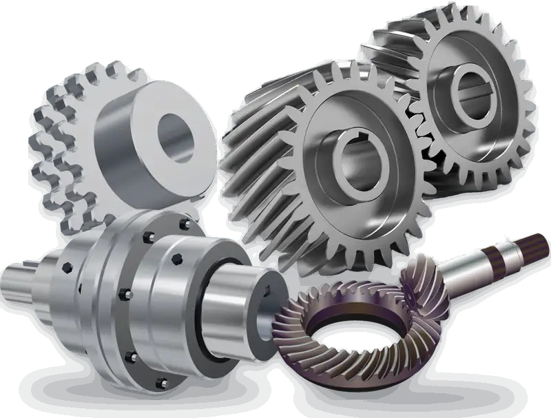
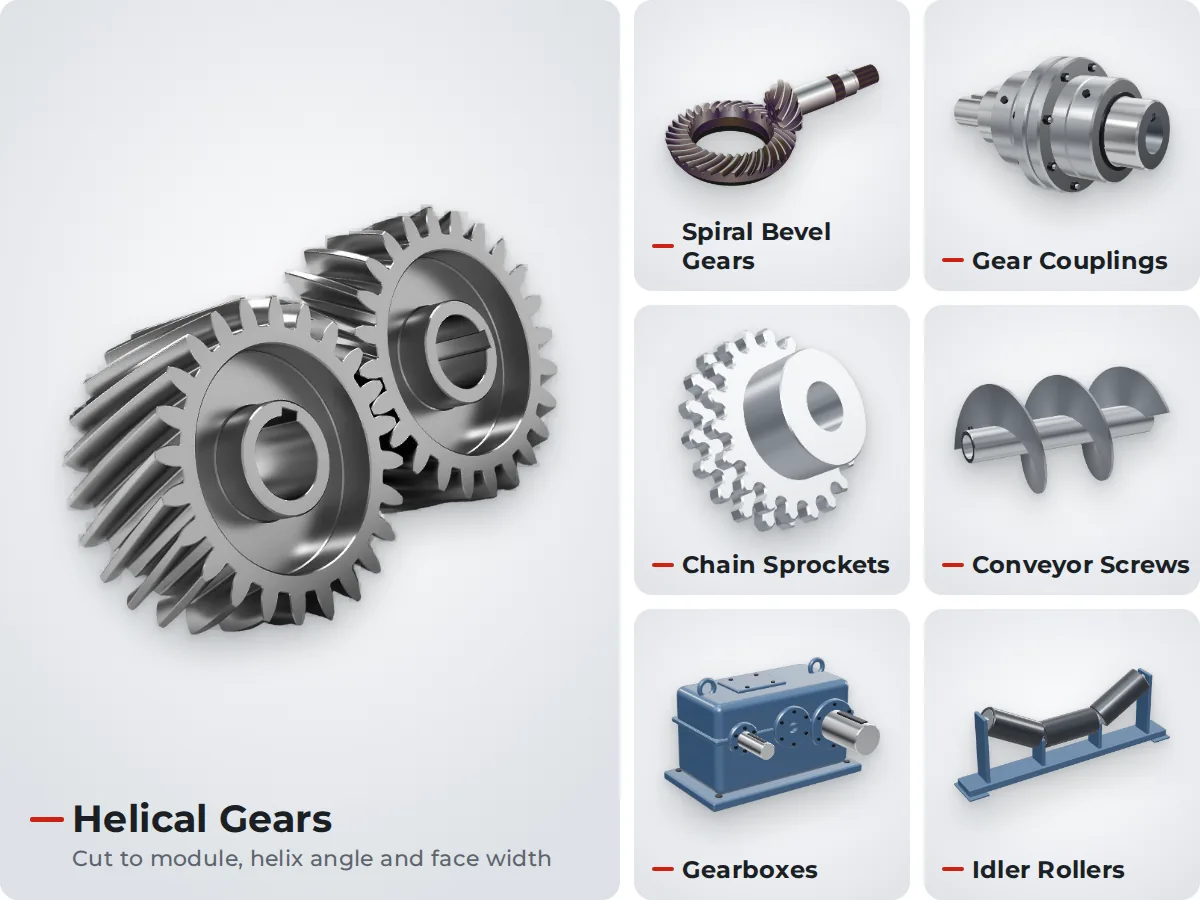
There are a number of common types of gears used in industry, these are:
- Spur Gears: Teeth which are parallel to the axis of the gear. A simple design which is used for parallel-shaft applications.
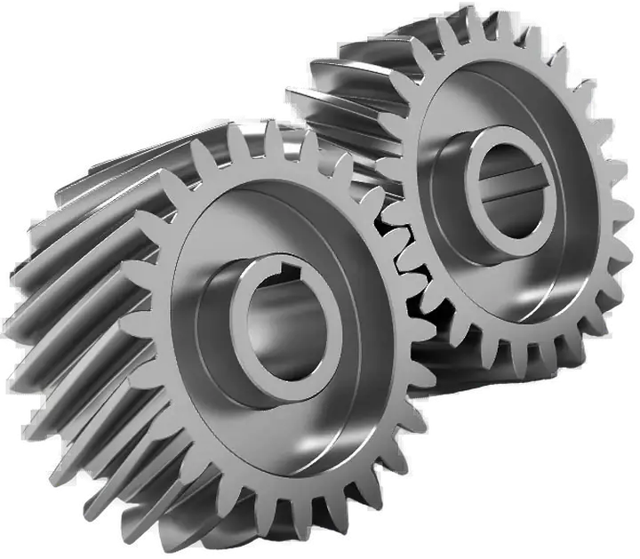
- Helical Gears: Has angled teeth and provides smoother and quieter operation, with improved load capacity.
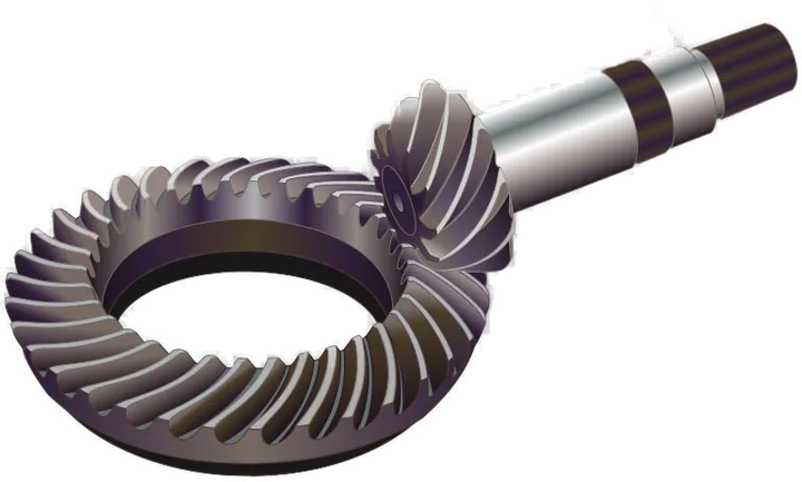
- Bevel Gears: These are gears that are used to transfer power between two shafts that intersect and to change the direction of power transfer.
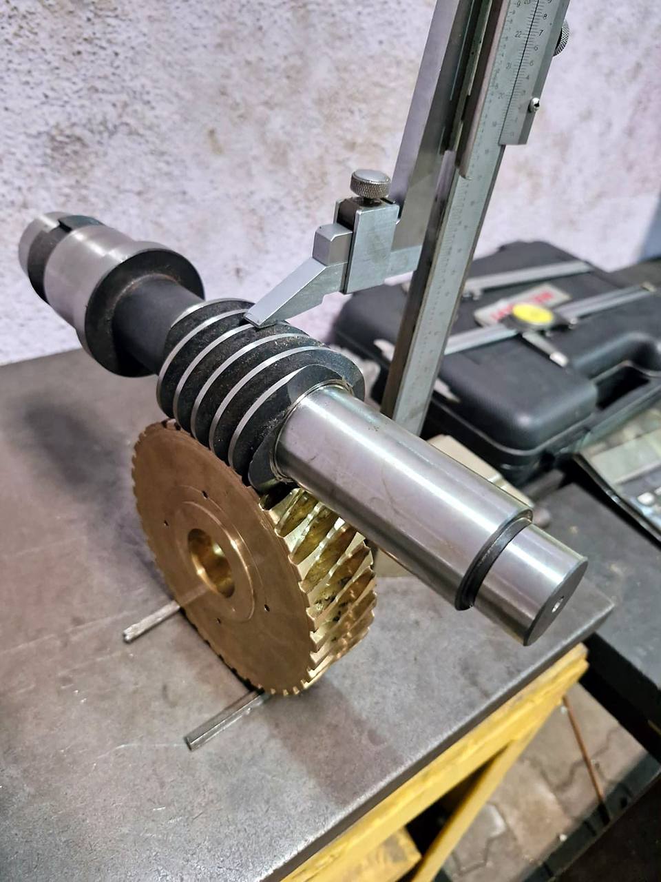
- Worm Gears: Worm and worm wheel – suitable for right angle applications and high ratio drives.
- Planetary Gears: A set of gears that transmit high torque in a compact assembly consisting of a sun gear, planet gears and a ring gear.
An industrial gearbox is a machine that is composed of gear sets, shafts, bearings, seals, lubrication and housing in one assembly. Typical gearboxes are parallel shaft, right-angle, helical, bevel-helical, worm and planetary gearboxes.
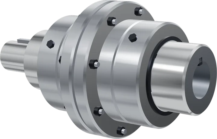
The two basic elements common to all of the gearboxes. Power is transmitted by gears, shafts transmit the rotation and bearings hold the shafts and minimise friction. This is made of cast-iron or fabricated mild steel which ensures that all components stay in place. The lubrication reduces wear and eliminates heat, the oil and contaminants are kept out of the gearbox by the seal, and the couplings connect the gearbox to the motors and driven equipment.
With regard to the gear geometry, tooth profile, material, heat treatment, gear ratio, speed of input and output shafts, transmitted power and torque, shaft arrangement, operating temperature and mounting arrangement, a lot of factors should be taken into consideration of a gear system design. But in critical applications, engineering and manufacturing are crucial to build a reliable service life.
Benefits of Choosing Us?
- Application Based Solutions: Each product is tested on the machine type, environment, power, speed, torque and installation requirements.
- Hands-On Engineering Approach: ASAR Engineering constructs transmission solutions with hands-on, industry-oriented engineering.
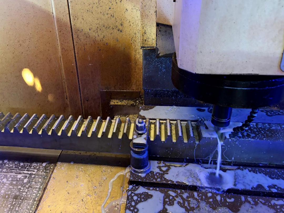
- Quality-Oriented Manufacturing: Dimensional accuracy, material selection, gear geometry, and manufacturing processes are all being taken care of to ensure consistent performance.
- Customer Options: Shaft sizes, shaft proportions, shaft configurations, mounting options, materials, lubrication, and housing options may be adapted to fit your needs.
- Strong Construction: To support the rigors of use, appropriate materials and construction techniques are used to build gear systems.
- Expert Technical Support: Communicate with the power transmission technical team to determine that a power transmission design is suitable for your application.
- Reliable Supply Coordination: Your project stays on track from enquiry to delivery with reliable coordination.
- Customer-Centric Service: The team will listen to your needs and assist you throughout the entire process, from initial discussion to final delivery.
Industrial Transmission Gear Specifications Table
|
Technical Parameter
|
Standard Range / Specification
|
Description
|
|
Gear Types
|
Helical, Spur, Bevel, Worm, Planetary
|
Configurations for parallel, intersecting, or right-angle shafts.
|
|
Transmissible Power
|
Up to 55,000 kW or higher for turbines
|
Maximum power capacity handled by heavy industrial units.
|
|
Output Torque
|
Up to 7,350 kNm
|
Rotational force capability delivered to the driven machine.
|
|
Center Distance
|
100 mm – 1,000 mm+
|
Distance between input and output shaft centers; ISO preferred numbers may be considered.
|
|
Rotation Speed
|
Up to 67,000 r/min for high-speed applications
|
Maximum rotational input/output velocity depending on design.
|
|
Pitch Line Velocity
|
Up to 176 m/s
|
Tangential speed at the pitch diameter of the gear teeth.
|
|
Machining Accuracy
|
ISO Grade 3 to ISO Grade 6
|
Precision grade influencing backlash, noise, and surface finish.
|
|
Efficiency
|
80% – 95%
|
Varies by gear type; spur/helical systems are generally more efficient than worm gears due to lower sliding losses.
|
|
Housing Material
|
Cast Iron or MS Fabricated
|
Housing may be split horizontally or vertically for easier internal maintenance access.
|
|
Lubrication
|
Splash/Oil Bath or Forced Circulation
|
Pump-driven or dip lubrication selected according to pitch line speed and mounting conditions.
|